The Lightning R-84 owner’s manual
Warning!
INTRODUCTION
This manual contains information on how properly to adjust and operate your Lightning bicycle for maximum comfort, safety, and performance.
The recumbent position and seat require alternate adjustment methods. The unconventional design and closeness of the front wheel to your feet require that new riding skills must be acquired.
Carefully follow the instructions, and after a short period of time, you will have the new habits needed to ride your Lightning successfully.
CONTENTS
1.0 R-84 ASSEMBLY
- 1.1 ASSEMBLY
- 1.2 FRAME KIT INFORMATION
2.0 ADJUSTMENTS BEFORE RIDING
- 2.1 CRANK ADJUSTMENT
- 2.2 HANDLEBAR ADJUSTMENT
- 2.3 REAR SUSPENSION PRELOAD
- 2.4 CHAIN ADJUSTMENT
3.0 RIDING
- 3.1 PEDAL TYPE
- 3.2 STARTING
- 3.3 SLOW SPEED TURNS
- 3.4 HANDLING AND STABILITY
- 3.5 PULLING ON THE HANDLEBARS
- 3.6 MUSCLE CONDITIONING
- 3.7 CLIMBING HILLS
- 3.8 SAFE RIDING
4.0 ACCESSORIES
- 4.1 WATER BOTTLE
- 4.2 REAR RACK
- 4.3 PANNIERS
- 4.4 SEAT BAG
- 4.5 MIRROR
- 4.6 AIR PUMP
- 4.7 ZZIPPER FAIRING
5.0 MAINTENANCE
- 5.1 THE SEAT
- 5.2 THE CHAIN IDLERS
- 5.3 PAINT
- 5.4 BIKE PARTS
- 5.5 ZZIPPER FAIRING
- 5.6 REAR SUSPENSION MAINTENANCE
- 5.7 SUSPENDED FORK MAINTENANCE
Note
1.0 R-84 ASSEMBLY
1.1 COMPLETE BIKE ASSEMBLY
- Remove all items from the box and unwrap. Be careful to support the handle bars so that the cables are not kinked.
- Install the steering column onto the fork.
- Install the rear derailleur. Install the wheels in the dropouts, and check the tire pressure. When installing the rear wheel, push down slightly on the seat back to fully engage the rear wheel axle into both dropouts.
- Loosely bolt the seat onto the frame using the included hardware (see Figure 1-1). It is recommended that the screws, and the seat where it contacts the frame, be coated with grease to prevent corrosion. Tighten all seat bolts tight.

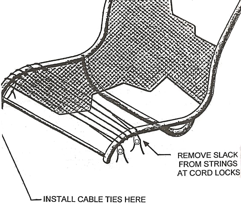
- Finish tying your seat bottom (see Figure 1-2), Slide the seat bottom fabric forward on the seat frame. Take the slack out of the strings, starting at the top and working down. The strings and fabric need to be very tight. The excess string can be taken up using the cord locks under the seat. Finally, connect the seat fabric to the small cross tube at front of the seat frame, using the included cable ties.
- Slide the cranks and bottom bracket assembly into the forward frame tube, and install the pedals. DO NOT APPLY ANY GREASE TO THE BOTTOM BRACKET EXTENSION TUBE, OTHERWISE, IT MIGHT ROTATE UNDER PEDDLING PRESSURE.
Adjust the crank length and tighten to 25 to 40 inch-pounds (28 to 46 cm-kgs).
Adjust the handlebar height and tighten. (See HANDLEBAR ADJUSTMENT.)
Caution!
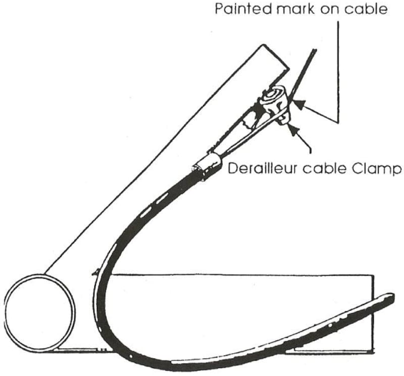
- Front shifter connection/adjustment: Rotate lever until the cable is fully released and thread cable to the derailleur. Figure 1-3 shows the cable installation for the front derailleur.
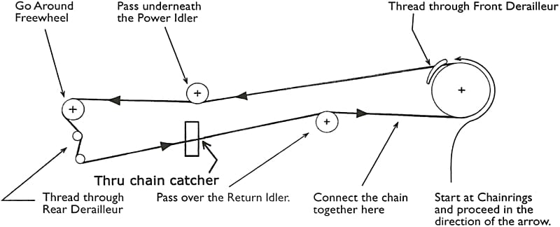
- Install the chain according to Figure 1-4. (See 2.0 ADJUSTMENTS BEFORE RIDING for proper chain length.)
- Re-check the headset, brakes, and derailleurs for proper adjustment and operation.
1.2 FRAME KIT INFORMATION
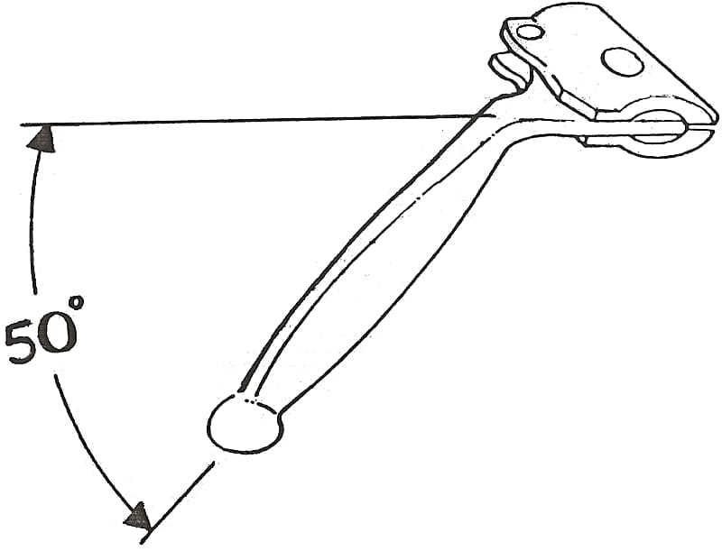
- Bend the Brake levers down as shown. The best way is to hold the upper part of the lever in the vise, heat the bend area with a propane torch and hit the end with a rubber mallet. Remember, the right and left sides are opposite (See Figure 1-5).
2.0 ADJUSTMENTS BEFORE RIDING
2.1 CRANK ADJUSTMENT
On Lightning bicycles, the cranks are moved to accommodate differences in leg length. Adjust the cranks as follows:
- Loosen the two Allen head bolts under the crank tube with a 5 mm Allen wrench.
- Slide the cranks in or out until your legs are slightly bent at their furthest extension (See Figure 2-1). It’s better to have the cranks too close when making the initial adjustment than too far away.
- Verify the crank arms are vertical by sighting along them to the handlebars stem, then tighten the two Allen head bolts to a torque of 25 to 40 inch-pounds (29 to 46 cm-kg).
2.2 HANDLEBAR ADJUSTMENT
- Slightly loosen the stem clamp using a 6 mm Allen wrench.
- Adjust the handlebars up or down so that there is approximately ½ inch of clearance between your knees and the handlebars (see Figure 2-1).
- Verify the handlebars are at right angles to the front wheel, then tighten the stem clamp.
- Slide the cable housing on the stem up or down to prevent any tight cables during turning.

2.3 REAR SUSPENSION PRELOAD
The rear suspension preload bolts are located under the chain stays (see Figure 2-2). These preload bolts are used to limit the initial amount of suspension movement, caused by the rider sitting on the seat. Note that when the rider sits on the seat, the rear suspension compresses, causing the rear rim to move upward and slightly forward, away from the rear brake pads.
Warning!
- Tighten the preload bolts so that, when the rider sits on the seat, the wheel only moves ⅓ the width of the rim, as seen at the brake pads (see Figure 2-2).
- Next, with the rider off the bike, adjust the brake pads so the fronts of the pads are aligned with the most forward part of the rim.

You will note that with the rider on the bike, the preload bolts lose tension and hang below the chain stays slightly; this is normal.
Note
2.4 CHAIN ADJUSTMENT
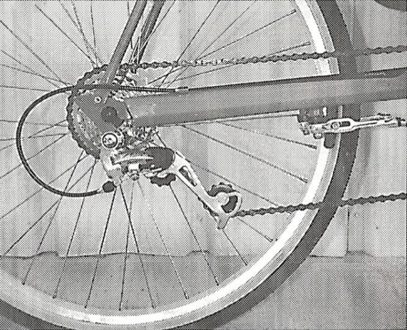
After adjusting the cranks, check and adjust the chain length. The chain should be long enough to permit shifting onto the large front chain wheel-to-large rear sprocket combination, and at the same time, not so long that it goes slack when shifted onto small chain wheel-to-middle rear sprocket combinations.
This can be accomplished by adjusting the chain length so that the rear derailleur is in the position shown in Figure 2-3 with the chain on the large chainring-large rear sprocket combination.
Caution!
Note
3.0 RIDING
Find a straight, level road without much car traffic for learning how to ride. DO NOT attempt any U-turns or other sharp turns until you have mastered slow speed turning (explained in Step 3.3). Keep your speed at 10 to 15 mph, as this will prevent your feet from hitting the front wheel and is more stable than slower speeds.
3.1 PEDAL TYPE
- Toe clips
- If your bike has standard pedals with toe clips, it helps to pedal on the back of the pedal while learning. Once you are ready to use the clips, hook the top of your shoe onto the end of the clip to rotate the pedal into position.
- Clipless pedals
- Don’t engage when first learning how to ride. Also, practice unclipping a few times before engaging clipless pedals. It is best if you practice while leaning against a wall, or while someone is holding you up.
3.2 STARTING
- If this is your first experience with a recumbent bicycle, it is suggested that a friend helps you balance by holding onto the seat when starting.
- For starting by yourself, the trick is to have one pedal in the straight up (power) position, with one foot on this pedal, and the other foot on the ground. Push hard against the upright pedal to get moving, then bring your other foot up and catch the other pedal.
3.3 SLOW SPEED TURNS
Warning!
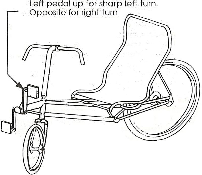
- The easiest solution is to coast through the turn and keep your foot in the up position on the side you are turning. For example: for a right turn, keep your right foot up (See Figure 3-1). This method requires you to have sufficient speed to coast through the turn.
- To make turns and apply power, have your feet as in (A) and make short ⅓ rotation, back and forth pedal strokes. This method must be used when you are starting out and turning at the same time, such as turning right after stopping at a stop sign.
Each method takes some practice to master, but will eventually become second nature. The interference is a problem only at speeds below 6 mph. Above this, the wheel is not turned enough to be a problem.
3.4 HANDLING AND STABILITY
The Lightning bicycle has fair stability and responsive steering. It is not necessary to aggressively hold onto the handlebars. A relaxed grip is best for riding in a straight line. One hand on the bars is adequate for relaxed cruising. As speed increases, the stability actually improves if maximum power is not applied to the pedals.
3.5 PULLING ON THE HANDLEBARS
Warning!
3.6 MUSCLE CONDITIONING
- DO NOT immediately ride your bike for long distances as it takes some time for your muscles to become accustomed to the recumbent position. Ride 5 to 10 miles on the first day, then increase by 5 to 10 miles per day thereafter. Your quadriceps and rear end muscles may be mildly sore while you are getting used to the bike. This is normal; it should disappear once the daily miles you ride stabilize.
- If your knees hurt constantly, this could be caused by improper crank adjustment. Try adjusting the cranks in or out slightly and see if the condition improves. Also, low RPM gear smashing can cause your knees to hurt.
3.7 CLIMBING HILLS
Use a lower gear and spin! If your pedaling speed drops below 60 rpm, then your power also drops off. Pulling on the handlebars does not help any.
One trick to try on long and/or steep hills for relief or extra power is this: Steer with one hand and push on your knee with your other hand as you pedal. As one arm gets tired, trade off and use the other one. This arm power
can add 10% more speed for short periods.
If you want to do extra training in order to climb hills better, then weight lifting (both upper and lower body), and one-legged pedaling on the flats (to develop your backstroke muscles) help significantly.
3.8 SAFE RIDING
- If for some reason you fall over while moving, DO NOT PUT YOUR FOOT DOWN. It can be drawn underneath the seat, causing severe injury to your leg and knee. Instead, keep your feet on the pedals, and let the seat take the impact.
- WEAR A HELMET! If your head is worth less than $50 (the price of a good helmet); you don’t need one.
- WET WEATHER: Your brakes do not work well in this condition, so allow for more stopping distance on downhills. Also, BE CAREFUL when cornering!
- CORNERING: BE CAREFUL cornering fast on unfamiliar roads. Any gravel in the corner may cause a slide-out. Because of the low seat position, it is possible to lean over more in a comer than a standard bike without realizing it.
- Try to observe all traffic regulations. Cars like it when you are predictable, so don’t make any sudden moves, and always signal your intentions.
- If you ride in heavy traffic, a warning flag may be a good idea. Bright colored clothes help also.
- For night riding, buy a good lighting system. NightSim has the best lights for dark roads at Lightning speed.
- BE CAREFUL on roads that have been repaved, leaving a lip where the new pavement drops off onto the old pavement at the shoulder. The small front wheel some time has problems negotiating this lip.
4.0 ACCESSORIES
4.1 WATER BOTTLE
One set of water bottle braze-ons is standard under the seat. We recommend using heavy duty (6 mm) aluminum cages, or the Specialized rib cage. A second water bottle can be carried on the stern by using a Blackburn handlebar cage, or a standard cage mounted using cable ties. Also, a Camelbak Halfback
can be mounted behind the seat.
4.2 REAR RACK
The custom made R-84 rack is required.
4.3 PANNIERS
The best panniers to use are the Lightning Zero Drag type. They give better weight distribution and do not increase drag like other panniers; They easily mount on the custom rack. However, any pannier that fits the rack will work.
4.4 SEAT BAG
Bags with straps that normally loop around handlebars can be used behind the seat. Carefully cut slots into the seat material so that the bag straps can be wrapped around the top seat tube. Be sure to seal the edges of the seat material using a hot piece of metal, to prevent unraveling. Another option is the Lightning seat bag, which holds a large amount, and can be simply slipped on over the seat back without the need for cutting slots.
4.5 MIRROR
The Mirrycle mirror which mounts to the left brake lever works well.
4.6 AIR PUMP
A mini pump is recommended.
4.7 ZZIPPER FAIRING
HARDWARE
- For fairing bubble installation (preinstalled):
- 1 small black plastic loop
- 4 large black plastic loops
- 5 black plastic screws
- 5 black plastic nuts
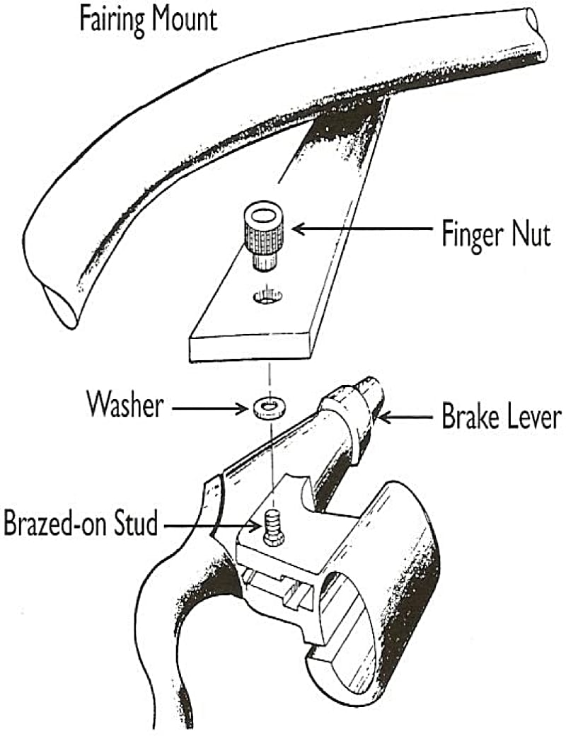
- For fairing mount installation upon the brake levers:
- 2 pivot bolts w/brazed-on stud
- 2 finger nuts
- 2 Washers
- Slide the Fairing Mount through the large black Plastic Loop Clamps (See Figure 4-1).
- Slide both ends of the Forward Support Hoop into the small holes of the Fairing Mount.
- Secure the small Plastic Loop Clamp around the Forward Support Hoop.

Note
- Remove existing pivot bolt from the brake levers. Using the included acorn nut, install the new lever pivot bolts with the brazed-on stud (See Figure 4-2). Next, space the brake levers so the studs match the fairing mount tabs.
- Bolt the fairing mount onto the brake levers using the included washers and nuts (See Figure 4-2).
- While sitting on the bike, spin the pedals backward and see how close your legs come to the bottom of the fairing. If your legs hit the fairing, you should adjust the fairing by pushing forward on the bottom of it. This will bend the mounting tabs to the proper angle.
5.0 MAINTENANCE
5.1 THE SEAT
The seat as received on new Lightning bicycles is fairly tight. After an initial break-in period of riding, the seat will loosen up due to stretching of the material. The seat back should be tightened by taking the slack out of the string that runs along the sides.
Note
5.2 THE CHAIN IDLERS
The chain idlers have sealed bearings and do not normally require maintenance. The idler under the seat develops a wear pattern to match the chain after a few thousand miles. This is normal and nothing to worry about.
5.3 PAINT
The paint on the frame is a urethane type automotive paint. It can be polished and waxed with ordinary auto type products if desired.
5.4 BIKE PARTS
All of the other parts are standard bicycle components and can be easily serviced by your local bicycle shop. The chain should be oiled periodically. The headset, bottom bracket, pedals, and hubs should be cleaned, greased, and adjusted once a year. The brakes and control cables should be monitored and adjusted when necessary.
5.5 ZZIPPER FAIRING
Lexan is an extremely tough and crack resistant material. The Zzipper fairing will withstand a great deal of abuse, even crashes, without breaking or cracking. However, it scratches easily. Thus, to preserve its appearance, these steps should be followed:
A) Clean the Zzipper fairing with Windex or a mild detergent solution and a soft rag. Never use solvents of any kinds.Tooth paste is a good compound for smoothing out minor tears.
B) Remove the Zzipper fairing when placing the bike on a bicycle carrier rack, unless the Zzipper fairing faces directly forward.
5.6 REAR SUSPENSION MAINTENANCE
Normally, the rear suspension does not require any maintenance. However, over a period of years, the elastomer suspension member may lose its elastic properties and remain in a compressed state. You will know this has occurred if the rear suspension no longer reacts to bumps.
5.6.1 To change out the elastomer, perform the following steps (See Figure 5-1):
- Remove the rear wheel.
- Remove the lock nut securing the swing arm pivot bolt.

Note
- Remove the pivot bolt by unscrewing it from the frame.
- Remove the preload adjusting screw.
- The swing arm and elastomer can now be removed from the frame.
5.6.2 To reinstall the rear suspension components, perform the following steps:
- Install the elastomer into the frame, then insert the preload adjusting screw through the hole in the elastomer to hold it into position.
- While holding the preload adjusting screw with one hand, insert the swing arm into the frame with the other; then screw the preload adjusting bolt into the captive nut in the swing arm. This takes a little practice. It is easier said than done!
- Install the pivot bolt with its washer, screwing it into the threads located on the inside of the chain stay.
Note
- Tighten the pivot bolt until it is snug, then loosen slightly. It is important to adjust the pivot bolt so that the swing arm can pivot up and down freely, but at the same time has no side-to-side play.
- While keeping the pivot bolt from turning, install and tighten the lock nut. Verify the swing arm still pivots freely, without any side play.
- Tighten the preload adjusting screw until resistance can be felt due to compression of the elastomer, then continue tightening the screw five more turns. This setting is a good starting point. Finally, perform 2.3
rear suspension preload
for final adjustment.
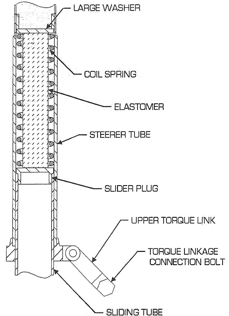
5.7 SUSPENDED FORK MAINTENANCE
Once a year, the sliding parts of the suspended fork should be disassembled and greased. Perform the following steps to accomplish this (Reference Figure 5-3):
- Remove the bolt holding the upper and lower torque linkages together, then pull the fork blades out from the steerer.
- Wipe off any dirt with a rag, then put a thin coat of Phil Wood or similar grease on the sliding parts.
- Reassemble the fork and install the bolt that holds the torque links together. Tighten the nut snug, then back it off ¼ turn.
- The dynamic parts of the suspended fork consist of a coil spring and an elastomer for damping. Eventually, the elastomer may wear out and require replacement. See Figure 5-3 for the location of the elastomer. To change the elastomer, follow steps A through D above.